
#Isolated cuk converter how to#
A hall sensor would have to be used, but they have poor bandwidth which would mess things up.ĭoes anyone know how to set the component values for this converter? The only advantage of this modified cuk converter appears to be that you can dispense with the mains diode bridge. The necessary fast current sense in the power FET loop will be difficult, because this will have to be transferred across an isolation barrier to the control chip, and this will be difficult. Then the sensed current and output voltage signals would need to be referred to this isolated ground. Therefore, an output of an isolated SMPS would need to be used to “ground” the controller to. The circuit would obviously need a controller to control it…but there is no “primary ground” to use to ground such a controller to. The problem is, where would you recycle the energy too?….since there is no storage capacitor on the primary side, and recycling to the secondary needs another isolation transformer. The transformer primary would need a heavy snubber, and this would be very dissipative, unless some kind of energy recycling snubber was implemented. If 元 is too high Henry-ic value, then the current throughput goes down and you can’t get the power throughput. If 元 has too low value then the peak current is too high.

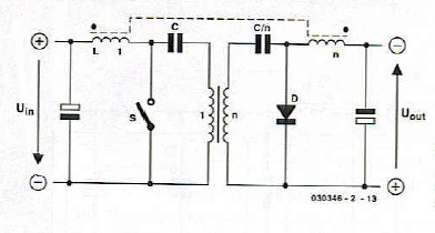
If C1 is too low Faradic value then C1 has too high voltage across it. I thought that the LC resonant frequency would need to be roughly at the switching frequency but that gives poor performance….the power throughput cannot be made high enough that way. The circuit is a resonant circuit, and 元 is the resonant inductor, and C1 is the resonant capacitor. I believe that this needs a energy recycling snubber to be used with it….so has Dr Cuk not given us enough information to implement his fantastic converter with? Perhaps he is understandably only divulging the basic detail? –not enough to achieve implementation? The attached LTspice simulation and schematic show an improved version of the special PFC circuit, but the voltage and/or current waveforms are too peaky in this converter…Īlso, the transformer is suffering enormous voltage spikes. Re: Is this this circuit going to revolutionise Switch Mode Power Supplies worldwide? The link is 4 years old, howcome nobody is doing this now?….why bother with a mains diode bridge and a downstream isolating converter if its not needed.? Here is the link to the pioneer of this breakthrough power supply circuit, and the details of it…. The attached is a simulation of our work so far of the Cuk converter. Why does this capacitor have to be of such big Faradic value?
#Isolated cuk converter series#
Why is the current in the L1 always discontinuous? Can this circuit not operate in Continuous conduction mode?Īlso, the series capacitor, C1, suffers 15 Amps of ripple current, and has to be rated to 600V (and must not be of polar type like an electrolytic), and has to be at least 100uF. The Cuk converter does the whole job by itself and needs no other circuits.ĭo you think this is possible? Dr Slobodan Cuk seems to think so (as in link below) This converter does not need a mains diode bridge before it, and does not need an isolating SMPS stage downstream of it. We wish to use the modified Cuk converter to do this.

We are doing a 3kW battery charger (Vin = 230VAC, Vout = 250 – 420VDC) Is this this circuit going to revolutionise Switch Mode Power Supplies worldwide?


 0 kommentar(er)
